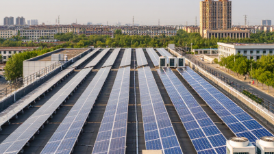
How to Install Solar Panels on Your Roof?

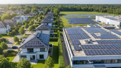
Learning how to install solar panels on roof begins with more than placing modules under the sun. A safe installation starts with a strong roof, accurate measurements, and a realistic energy assessment. You must also understand your home’s electrical system, panel orientation, shading patterns, and local permitting requirements.

This guide explains the practical stages, from checking rafters and selecting mounting hardware to connecting the inverter and arranging inspections. It reflects common recommendations from solar professionals, roofing specialists, electrical standards, and utility procedures. A qualified installer should verify every critical connection. Solar work involves serious fall, fire, and electrical risks.

Small details matter. A cracked tile, loose flashing, or shaded chimney can change the entire plan. Roof age matters too. Installing panels over worn shingles may create expensive problems later. The process is not perfectly neat. Weather can delay work, measurements can need revision, and online calculators may produce optimistic estimates. That is worth remembering.

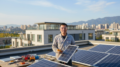
You will also learn when professional help becomes essential. Some homeowners can compare quotes or monitor energy use, but structural assessments and grid connections often require certified experts. Clear documentation helps, including equipment specifications, warranty terms, permits, and maintenance instructions. With careful planning, installing solar panels can become a dependable home improvement rather than a rushed purchase. A cautious start saves trouble.
How to Install Solar Panels on Your Roof?

Assess Roof Life, Orientation, Shade, and the 15°–40° Tilt Range

How to Install Solar Panels on Your Roof?

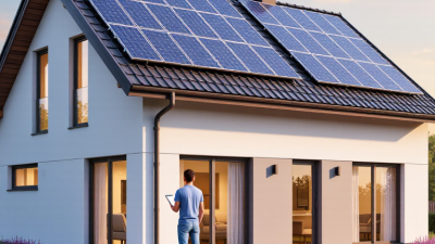
Before installation, inspect the roof’s age, structure, and waterproofing. Panels can last over two decades, so an aging roof may need repairs first. Replacing shingles beneath installed equipment is costly and disruptive. Look for curling materials, soft decking, leaks, and rust around fasteners. A qualified roofing or solar professional should assess load capacity, especially on older buildings. I would not trust a quick visual check alone.

Roof orientation strongly affects yearly production. In the Northern Hemisphere, an equator-facing roof usually receives the most useful sunlight. In the Southern Hemisphere, the opposite orientation often performs better. Nearby trees, chimneys, and taller buildings can create shade, even on bright days. Check shadows during morning, midday, and late afternoon. Winter shadows matter too. A small shaded area can reduce the output of an entire panel string, depending on the system design.

A roof tilt between 15° and 40° is commonly workable for solar panels. The best angle depends on latitude, seasonal sunlight, drainage, wind, and the roof’s existing pitch. Flatter roofs may need mounting frames, but extra height can increase wind exposure and visual impact. Steeper roofs can improve winter collection, yet they may complicate safe access. The range is helpful, not magical. I once underestimated late-afternoon shade in a site review; a second survey changed the panel layout. Measure carefully, document assumptions, and verify the final design with local structural and electrical requirements.

Estimate Array Capacity: Allow 6–10 m² of Roof per 1 kW of PV

How to Install Solar Panels on Your Roof?

Estimating array capacity starts with usable roof area, not the roof’s total footprint. Allow about 6–10 square metres of roof for each 1 kW of photovoltaic capacity. A 5 kW system may therefore require roughly 30–50 square metres. Measure the usable roof. Space disappears quickly around chimneys, vents, skylights, gutters, and required maintenance pathways.

The wider range reflects real roof conditions. A clear, south-facing section may approach 6 square metres per kW, while shaded or fragmented surfaces need more space. Roof direction, pitch, seasonal shadows, and panel layout all affect the result. Draw a simple plan and mark obstacles with their actual dimensions. It may look generous on paper, yet the final arrangement can feel surprisingly tight.

A qualified solar professional should verify structural strength, wind exposure, electrical capacity, and local installation requirements before work begins. They can also check whether nearby trees shade the array during winter. Do not size panels from area alone. In practice, a roof can support the desired capacity but produce less energy than expected. That is an uncomfortable possibility. A careful survey may reduce the proposed system, and that is often better than forcing panels into poor positions. Leave room for safe access, drainage, and future repairs. Reliability begins with an honest measurement, not an optimistic estimate.

How to Install Solar Panels on Your Roof?

Estimate array capacity by allowing approximately 6–10 m² of usable roof area per 1 kW of photovoltaic capacity.

The chart estimates the potential PV system size for different usable roof areas. Actual capacity may vary because of roof orientation, shading, panel layout, access pathways, and local installation requirements.

Prepare Permits, String Design, and DC/AC Protection to Local Codes

How to Install Solar Panels on Your Roof?

A safe rooftop installation begins with permits, not panels. Check your local building, electrical, and fire requirements before ordering equipment. Your authority having jurisdiction may request structural drawings, a single-line diagram, and equipment specifications. The utility may also require an interconnection application and inspection. Keep every approval accessible on site.

String design needs careful electrical calculations. Count modules in each string, then compare open-circuit voltage with the inverter’s maximum input during the coldest expected morning. Confirm operating voltage stays within the inverter’s tracking range. I once underestimated winter voltage during an early design review. That mistake could have caused expensive redesign work. Roof direction, shading, cable length, and service-panel capacity also affect the layout.

Tips: Label every circuit clearly. Use correctly rated DC fuses, disconnects, and overcurrent protection where required by local code. Install rapid-shutdown equipment when your jurisdiction requires it. On the AC side, provide suitable disconnecting means, grounding, surge protection, and a dedicated connection point. Keep DC and AC conductors separated, protected from sharp edges, and secured beneath the array. A licensed electrician should verify torque settings, insulation condition, polarity, and grounding continuity before energizing the system. Photograph concealed connections before closing access areas. Inspectors appreciate clear evidence, and future maintenance becomes less uncertain.

Install Flashing, Rails, Modules, and Grounding with Sealed Penetrations

How to Install Solar Panels on Your Roof?

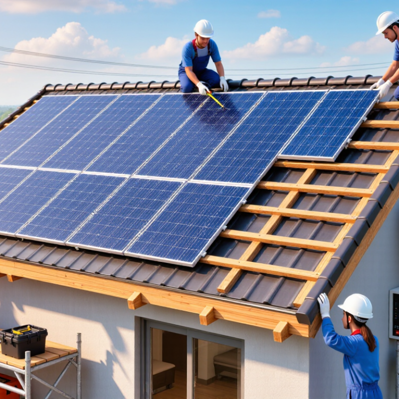
A sound roof installation begins with flashing, not the modules. Locate rafters with plans and a stud finder. Mark every attachment point carefully. In field practice, I recheck measurements because one misplaced penetration can create years of leakage risk. Slide flashing beneath the upper shingle course and over the lower course. Keep the sealant compatible with roofing materials. Do not rely on sealant alone.

Install rails straight, level, and firmly connected to structural members. A slight alignment error can stress module frames and complicate wiring. Follow the manufacturer’s torque values with a calibrated wrench. The International Energy Agency Photovoltaic Power Systems Programme reported over 400 GW of new photovoltaic capacity in 2023. More installations make consistent workmanship increasingly important.

Mount modules without forcing their frames into position. Leave the specified spacing for thermal movement and drainage. Bond rails and module frames using approved grounding hardware. Route conductors neatly, away from sharp edges and standing water. Seal cable penetrations with a listed flashing assembly, not a casual blob of roofing compound. I still inspect the attic after the first rain. That step feels slow, but hidden moisture is easy to miss. Final checks should include fastener torque, roof drainage, conductor protection, and electrical continuity. Local electrical and building requirements must guide the work.

How to Install Solar Panels on Your Roof? — Install Flashing, Rails, Modules, and Grounding with Sealed Penetrations
Installation Stage Primary Components Typical Specifications or Dimensions Installation Method Key Quality and Safety Checks
1. Roof Assessment and Layout Roof structure, roofing material, rafters or trusses, array layout Confirm roof slope, available area, shading, access paths, and structural condition before work begins. Locate structural members and mark the planned module rows, rail positions, setbacks, and cable routes. Verify that the roof can support the added system loads and that local permits and electrical requirements are addressed.
2. Rafter and Attachment Point Marking Mounting feet, structural fasteners, chalk line, measuring tools Attachment spacing is determined by the rafter layout, roof design, wind exposure, snow loads, and the mounting system instructions. Mark each attachment location directly over structural members; avoid relying only on roof sheathing for structural support. Use approved fasteners of suitable length and corrosion resistance. Confirm every attachment is centered on solid structural material.
3. Flashing Installation Metal or polymer flashing, mounting feet, roofing sealant, structural fasteners Flashing should extend beneath the upper roofing course and over the lower course to preserve water-shedding layers. Temporarily lift or remove the necessary roofing material, position flashing over the attachment point, and fasten the mounting foot through the flashing. Flashing must not be installed upside down or trapped above the roofing layer. Follow the roof material manufacturer’s approved detailing method.
4. Sealing Roof Penetrations Roof sealant, sealing washers, EPDM or compatible gaskets, pipe or cable entry seals Sealant is a secondary water barrier; the flashing and shingle or membrane integration provide the primary drainage path. Apply sealant only where specified, install sealing washers or gaskets correctly, and tool the sealant to prevent water pockets. Inspect for gaps, exposed fastener holes, cracked sealant, and blocked drainage paths. Do not depend on surface sealant alone for long-term waterproofing.
5. Rail Installation and Alignment Aluminum rails, rail splices, clamps, mounting feet, end stops Rail spacing must match the module manufacturer’s permitted clamp zones and the structural design for local wind and snow conditions. Attach rails to the mounting feet, leave required expansion or splice clearances, and align rails parallel to the roof layout. Check rail straightness, fastener torque, splice placement, cantilever limits, and clearance from roof edges and obstructions.
6. Module Placement Solar modules, mid-clamps, end-clamps, module frames Maintain the module manufacturer’s required clamp position and inter-module gap; a common gap is approximately 10–20 mm, but the approved instructions control. Place modules on the rails, secure the first module with end-clamps, connect adjacent modules with mid-clamps, and complete each row. Avoid walking on modules, pinching cables, blocking drainage channels, or overtightening clamps. Confirm all clamps engage the frame correctly.
7. Module Cable Management Module connectors, cable clips, UV-resistant ties, cable trays or conduit Keep cables clear of the roof surface, sharp edges, standing water, and areas where they could be damaged by movement or heat. Route cables along the rear of the array, secure them to the mounting system, and maintain connector polarity and proper separation. Inspect connectors for complete engagement, compatible mating parts, correct polarity, and strain-free routing. Never leave connectors lying in water or soil.
8. Roof-to-Wall or Roof-to-Conduit Entry Weatherproof cable entry enclosure, conduit, flashing boot, compression fittings Entry locations should avoid low areas where water accumulates and should maintain the roof’s drainage and weatherproofing layers. Use a purpose-designed entry seal or flashed penetration, route conductors through approved conduit, and secure conduit to prevent movement. Confirm the entry is watertight, mechanically supported, UV-resistant, and protected from abrasion. Seal unused openings with approved closures.
9. Equipment Grounding and Bonding Equipment grounding conductor, bonding hardware, grounding lugs, rails, module frames Grounding conductor size and connection method depend on system design, overcurrent protection, local electrical rules, and the equipment instructions. Bond exposed metal module frames and rails using listed bonding hardware, then connect the equipment grounding path to the building’s grounding system. Verify continuity across rails, module frames, enclosures, and the grounding electrode or grounding system. Do not use bonding hardware as a substitute for the required conductor.
10. Electrical Testing and Commissioning DC isolator, overcurrent protection, inverter or power conversion equipment, test meter Expected voltage and current depend on the series and parallel configuration; test values must remain within equipment ratings. Complete visual inspection, polarity testing, open-circuit voltage checks, insulation or continuity tests where required, and controlled energization. Qualified personnel should perform electrical testing. Record test results, labels, circuit identification, and emergency shutdown information.
11. Final Roof and Hardware Inspection Flashing, sealant, fasteners, rails, clamps, modules, conduit All components should be secure, corrosion-resistant, compatible with the roof, and installed without obstructing roof drainage. Review every attachment, flashing location, clamp, cable route, conduit support, and roof transition from the ground and roof level where safe. Look for loose hardware, damaged roofing, exposed sharp edges, incomplete seals, unrestrained cables, and missing labels or protective covers.
12. Documentation and Maintenance Plan As-built layout, electrical diagram, inspection records, maintenance schedule Keep records of module arrangement, circuit paths, grounding points, equipment ratings, test results, and roof penetration locations. Provide system documentation and establish periodic visual inspections, especially after severe weather or roof work. Monitor for water intrusion, corrosion, damaged wiring, loose clamps, debris buildup, and abnormal system performance.

Commission the System and Verify Its 75–85% Performance Ratio

How to Install Solar Panels on Your Roof?

Roof installation is only half the work. Commissioning proves whether the finished system performs safely and consistently. A qualified installer should inspect roof attachments, cable routes, grounding, connectors, and weather seals. Every panel circuit needs polarity and insulation checks before energizing the inverter. Record these results with photographs and test readings.

Performance ratio, or PR, compares delivered energy with the energy theoretically available from the sunlight received. A practical annual target is often 75–85%, depending on climate, roof angle, shading, temperature, and equipment losses. During commissioning, measure plane-of-array irradiance, module temperature, DC voltage, DC current, and AC output. Enter the exact panel capacity and test conditions into the monitoring report. Do not judge the system from one cloudy afternoon.

The first result may look disappointing. That is normal. Early readings can be distorted by low sunlight, temporary construction dust, or incomplete monitoring data. Check the meter against a calibrated irradiance instrument, then compare production across several clear days. Persistent low PR may indicate shading, soiling, inverter clipping, loose connections, or incorrect system settings. A technician should trace the fault rather than adjust the target. I would also question an unusually high PR, because incorrect capacity data can make a weak system appear successful. Keep monthly records for the first year, including weather and cleaning dates. The roof may look finished, but the evidence is still developing.

logo

SOLARIC Showroom Address:
54 E. Rodriguez Jr. Ave (C5), Warehouse #9, Bagong Ilog, Pasig

Schedule: Monday to Friday 7AM to 5PM. Saturdays 8AM to 3PM.

Solaric Corp. (by appointment only)
15/F Jollibee Tower, F. Ortigas Jr. Cor Garnet Rd., Ortigas Center, Pasig

Email: [email protected]

Cell/Text: +63-917-860-3141 | +63 908 377 5577

Solaric Equipment

For Solar Professionals, Contractors, and Installers

Call / Email to reserve/pickup/ request delivery: Monday to Friday 7AM to 5PM. Saturdays 8AM to 3PM

© 2013 - 2026 Solaric Corp. All Rights Reserved